Showing posts with label USB Audio. Show all posts

Tuesday, March 14, 2017

Tympan Electronics and Its Self-Noise

After measuring the audio performance of the Teensy Audio Board (see my previous post), I felt that I needed something better.  If I wanted my open-source hearing aid ("Tympan") to sound good, I needed a quieter audio interface with a bigger dynamic range.  So, with help from friends and colleagues, I decided that we should build our own.  Today's post gives a quick overview of its design and then I'll present some measurements of its performance.  Were we successful?  Were we able to get better dynamic range?  Let's find out...


The Audio Codec is the Heart:  The picture above shows the Tympan audio interface.  The heart of the board is the audio codec at the top-center.  An audio codec is a highly-integrated chip that, among other duties, does all of the amplification and digitization of the incoming analog audio signals.  Choosing the right codec and then properly designing the circuit board around it are both key elements to achieving a low-noise design with maximum dynamic range.

Choosing an Audio Codec:  The Teensy Audio Board uses the SGTL5000 audio codec.  Presumably it was chosen because it is small, low-cost, low-power, and has a built-in headphone driver.  For my Tympan audio interface, I want all these same features, but I also want it to be quieter.  After looking at a bunch of options, and after talking with colleagues who have experience with a variety of TI parts, we chose to go with the Texas Instruments TLV320AIC3206 (product page here).  It's got many of the same features as the SGTL5000 but promises better audio performance, though at the cost of a few extra bucks per chip.  If it gets me the wider dynamic range that I want, I'll be very happy with that trade-off.

Circuit Design:  Like with the SGTL5000 on the Teensy Audio Board, the TI 3206 needs both the I2C and I2S buses to communicate with the host processor (the host processor being a Teensy 3.5 or 3.6).  Also like the Teensy Audio Board, we will run the TI 3206 in "slave" mode, where all clocking is provided by the host processor.  In other words, our connections to the TI 3206 parallel the connections used by the SGTL5000.  Therefore, in designing our Tympan circuit, the schematic for the Teensy Audio Board was a great help.  Yay for open source!  And, to continue the sharing, our own schematic is available on the Tympan GitHub here.


Software Driver:  After laying out the PCB and getting it fabricated, we had to write software to allow the Teensy and the TI 3206 to talk to each other.  Since I wanted to fit within the Teensy Audio ecosystem, we needed to write a "AudioControl" module that configures the TI 3206 to be in the proper I2S mode so that Teensy's existing I2S functions can successfully transfer audio data to and from the codec.  Luckily, I've got a buddy (Brendan, of FlexVolt fame!) who dived in and figured it all out.  His Arduino/Teensy compatible "AudioControl" module is now on the Tympan GitHub (h-file is here, cpp file is here).  Thanks, Brendan!

Measuring the Self Noise:  Once Brendan got the software side of things working [and, in the process, finding errors in the Tympan design -- we erroneously swapped "DIN" and "DOUT" by accident!  Oops!  The schematic above has been corrected.], I turned my attention to measuring the new system's audio performance.  My primary concern was the noise floor of the new hardware.  Was it better than the Teensy Audio Board?  To find out, I used a raw 3.5 mm stereo plug in the Tympan's input jack and shorted both the left and right inputs to ground.  Now, when I start recording, I should only see the Tympan's own self-noise.


Arduino Sketch:  Now I need some software to do the actual recording.  So, starting from the Arduino sketch used to record the noise for the Teensy Audio Board (here), I swapped it over to use the Tympan audio board instead of the Teensy audio board (new version here).  This sketch digitizes the input audio (which has been shorted to ground) and sends the digital samples over USB to be recorded on the PC.

Results, USB Audio:  With the inputs shorted on my Tympan board, and with me recording the audio via USB in Audacity (as discussed here), I recorded the self-noise of the Tympan.  The spectrum of the self-noise is shown below.  It's a pretty flat spectrum, which is always nice to see.  The only unexpected feature is the increase in the noise seen at the highest frequencies.   What is that?
It's a pretty nice spectrum, except for the bump up at the high frequencies.  What's that?!?
USB vs SD:  The recording above was taken via USB.  Therefore, the USB cable was attached to the Teensy/Tympan.  USB cables are notorious for injecting noise.  Frankly, I surprised that the spectrum shown above is as low and as flat as it is.  To see if the USB connection was the cause in the bump at the higher frequencies, I revised the sketch to record the audio to the Teensy's SD card instead of sending it over USB (new sketch is here),  Re-running my test, I see that the high-frequency hump is gone!  Now that's a beautifully flat spectrum...
By disconnecting the USB cable and recording the audio via SD card, the bump in the spectrum goes away.  Now the self-noise is nice and flat.  Excellent.
Noise Floor Comparison:  My primary goal for the Tympan board was to have a lower the noise floor (and thereby increase the dynamic range) than I saw with the Teensy Audio Board.  To see if I was successful, I used my recordings to compute the total self-noise across the frequency range of 125-8000 Hz. This is the frequency range most relevant for my hearing aid work.  I assessed this broadband self-noise value for the Teensy and Tympan boards across a range of analog gain settings.  The result of this noise analysis is shown in the figure below.
Apples-to-Apples:  The Teensy and Tympan boards have different ways of specifying the input gain.  Ideally, I'd be able to set the same amount of gain for each board, but that wasn't possible.  So, to  align the data in the most fair way, you can see that plot the values as function of the "maximum allowed input signal".  As expected, increasing the gain decreases the max allowed input.  So, at any given value for max allowed input, it is a fair to compare between the two systems.  As can be seen, the Tympan audio board does indeed have lower noise than the Teensy audio board.

Dynamic Range Comparison:  Another way to express this same data is to show the dynamic range of the system.  The dynamic range is the difference between the max allowed input signal and the system's noise floor.  I want as wide a dynamic range as possible, so as to better mimic the human ear.  As can be seen below, the Tympan audio board does indeed provide greater dynamic range than the Teensy audio board.  Specifically, the Tympan is getting 92.4-94.6 dB of dynamic range (in the 125-8000 Hz band) versus 80-81 dB for the Teensy Audio Board.  This is quite an improvement!
Keeping Perspective:  While I am very pleased with the performance of the TI 3206 on the Tympan audio board, it's important to remember that the Teensy audio board has some significant advantages in other areas.  First, you can go buy your own Teensy Audio Board right now, whereas you can't (yet) get a Tympan.  Second, the Teensy Audio Board is remarkably inexpensive.  It's hard to see the Tympan board ever being that inexpensive.  Yes, PJRC did a fantastic job making a good piece of hardware at a fantastic price.  That's for sure.

Next Steps:  I'm going to use the Tympan as a platform for open source hearing aid experiments.  But, a hearing aid is more than just electronics.  So, my next steps are to start adding in other elements like microphones and earphones.  And, I have to get back to making audio processing algorithms!  That's where the fun really happens!

Sunday, March 12, 2017

Teensy Audio Board Self-Noise

When working with audio, one typically wants as quiet a system as possible -- no one likes listening to hiss.  So, when I started working with the Teensy and the Teensy Audio Board, I applied a critical ear to the board's performance.  While the Teensy Audio Board was very fun, quite easy to use, and relatively inexpensive, I found that it was noisier than I like.  In this post, I'm going to illustrate the noise levels that I recorded and I'll show a workaround that helped remove a lot of that noise.


Setup:  For these tests, I used a Teensy 3.6 attached to Teensy Audio Board.  I then wrote an Arduino sketch (shared on my GitHub here) that would record audio from the line-in and send it to both the headphone output as well as to the USB Audio output.  I recorded the digital audio coming through USB using Audacity (as discussed here).  As shown in the picture above, To try to isolate just the self-noise of the system, I shorted the inputs using a jumper across the Teensy Audio Boards line-in terminals.  This should be as quiet as it can get.

First Results:  The audio that I recorded (shared here) sounded funny to my ear.  If I turned it up, I could hear a very annoying unsteady whining noise.  Looking at the spectrum (see plot below), I could clearly see some narrowband tones starting around 2 kHz.  That's right where one's hearing is most sensitive, which makes this kind of self-noise particularly problematic.  It's definitely not what you want if you're trying to make a hearing aid type of device.  What could be the cause of this?

Disable the ADC's HP Filter:  After a bunch of messing around, I finally stumbled across this post on tthe Teensy forum.   Here, "Raj" stated that the SGTL5000 audio codec (which is at the heart of the Teensy Audio Board) has a high-pass filter in its ADC.  He said that this HP filter was introducing a lot of noise and he shared the command for disabling that filter.  When I put the command "adcHighPassFilterDisable();" into my sketch and re-ran my tests, those annoying narrowband tones in the Teensy Board's self-noise went away (audio file here).  Ahhh.  That's so much better.

Varying the Gain:  The data shown above were taken with the input gain of the Teensy board set to "10" (ie, full-scale input spans 0.56 Vpp).  There are other gain settings that one could use.  So, I repeated my measurements at other gain levels to see if the input-referred self-noise was better or worse.  The results are below.

 As can be seen, the noise with the HP filter (the blue line) is noisier in all cases than when the HP filter is disabled (orange line).  So, as long as you can handle a little DC offset in your audio data, you should definitely disable that filter.

A second finding is that the apparent (input-referred) self-noise goes down as the gain increases.  So, if you have really quiet signals that you're trying to record, turning up the gain might help reveal those signals.

Dynamic Range:  The trade-off with turning up the gain is that the maximum signal level that can be recorded without clipping also goes down as the gain is increased.  For many applications, therefore, it is just as important to look at the dynamic range for the system.  The dynamic range is the difference between the maximum input level and the noise floor.  When I run the numbers for the Teensy Audio Board, I get the results below.

Here, I see that, when the HP filter is disabled (the orange line), the Teensy Audio Board has about 81 dB of dynamic range.  And, I also see that the dynamic range is basically independent of the gain setting.

Is it Good Enough?  So now we're down to the hard question:  is 81 dB of dynamic range good enough for my needs?  Well, it is a pretty decent number, especially for the price of the Teensy Audio Board.  But, for my use as part of an open-source hearing aid, where I need to amplify quiet sounds while not distorting on already-loud sounds, I think that I need a bigger dynamic range.  Normal human hearing spans on the order of 120 dB of dynamic range.  I think that I need hardware that'll get me at least a little closer to that number.

Motivation for a New Board:  The results shown here were my motivation for building the audio interface (the "Tympan") that I introduced in my last post.  In my next post, I'll share some details of that audio interface and I'll perform these same self-noise measurements to see if I was able to get a wider dynamic range.  Making wide dynamic range systems isn't easy, so it'll be exciting to find out how I did!

Follow-Up:  I measured the self-noise and dynamic range of the new Tympan board.  It's pretty good!  If you're interested, you can see the results here.

Tuesday, January 17, 2017

Basic Dynamic Range Compressor

My last post described the need for dynamic range compression in hearing aids: if you amplify enough to hear quiet sounds, loud sounds will become too loud.  One solution is to include a Dynamic Range Compressor (DRC), which changes the gain depending upon the loudness of the signal.  Because of the DRC, loud sounds will be amplified less than quiet sounds.  Perfect!  In this post, I describe how I implemented a DRC and I show its effect on some simple signals.

Algorithm Overview:  In the figure above, I illustrate the basic signal flow through my DRC algorithm.  It's a feed-forward design with a side-chain that computes the time-varying amount of gain that should be applied.  The function of each block is described below:
  • Pre-Process Signal:  In this block, I apply the "pre-gain", which is the amount of gain that will be applied when the compressor is in its linear regime.  Also in this block, I use a high-pass filter to remove any DC offset in the audio signal.
  • Level Estimator:  For the compressor to vary the gain based on the loudness of the signal, it needs to first estimate the loudness of the signal.  That's what this block does.
  • Gain Calculator: Using the estimated loudness, this block calculates how much to reduce the gain of the system.  It calculates the desired gain reduction knowing the "compression ratio" and "compression threshold" that have been supplied by the user.  It also smooths the compressed gain value through time via "attack" and "release" time constants that have been supplied by the user.
  • Apply Gain: Once the desired compressed gain value has been calculated by the side-chain, this block applies the gain to the audio signal.
Arduino/Teensy Implementation:  I implemented this algorithm as an C++ class that can be called from any Arduino or Teensy program (see AudioEffectCompressor_F32 in my GitHub library here). It is built upon my F32-extension of the Teensy Audio Library.  Because it is so reliant on floating-point operations, it is probably only appropriate for use on the Teensy 3.5 or 3.6 (which have floating-point hardware support) and not the older 3.0, 3.1, or 3.2.


Algorithm Parameters:  In the signal flow diagram below, I show the algorithm parameters that are available for the user to set.  The main tricky part is how to set the time constant for the Level Estimator.  By default, I have this value always scale itself to be 20% of the time constants that the user has set for the Gain Calculator block.  If you don't like this default behavior, you can specify your own value using the method setLevelTimeConst_sec().

Example Sketch:  As part of including this DRC algorithm in my OpenAudio_ArduinoLibrary (GitHub page here), I made sure to include an example sketch called BasicCompressor_Float.  This example code assumes that you have a Teensy Audio Board along with a Teensy 3.5/3.6.  Within the code, there are a couple of options:

  • USB Audio:  For my testing, I chose to send and receive audio over the USB link, instead of via analog audio cables.  See this post, if you want more info on how to use the Teensy's USB Audio link.  To enable USB audio in this sketch, set DO_USB to a value of one.
  • Fast or Slow:  Another choice is how to set the values for the compressor's parameters.  In my example, I have two sets of parameters.  One set gives a "fast" compressor response that is appropriate for quick limiting of very loud sounds.  The other set of values gives a "slow" response that can be used as a automatic volume control.  For my testing, I chose to use the "fast" response, as shown below.


Test Setup:  For my testing, I'm using my breadboard prototype of my Teensy Hearing Aid, which is just a Teensy 3.6 with the Teensy Audio Board (plus microphones, battery, and Bluetooth module, which are not relevant to this test).   I've got it plugged into my laptop via USB, which is also used to send and receive audio to the Teensy via the Teensy's ability to do USB Audio.  On my laptop, I'm using the Arduino IDE to set the compressor's parameters (again, I'm using the "fast" configuration) and I'm using Audacity to send the audio to the Teensy and to record the audio returned by the Teensy.


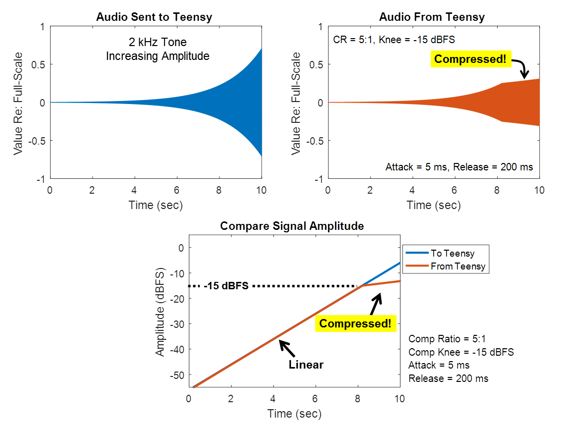
Testing, Amplitude Sweep:  For my first test, I generated a steady 2kHz tone whose amplitude increases from quiet to loud at a rate of about 6 dB/sec (my test signals are shared here).  This is the signal that I'm sending to the Teensy (also shown in blue in the figure below).  When sending this signal, the compression algorithm on the Teensy returns the signal shown in orange.  If you look at the loudest portion of the audio (starting around time = 8 seconds) the amplitude of the orange output signal looks to be squashed compared to the blue input signal.  This is the effect of the compressor!  It successfully reduced the dynamic range of the audio, as intended.

Quantifying the Response:  One important question is whether the compressor kicked in at the correct amplitude.  To answer this question, I assessed the instantaneous amplitude of each signal, as shown in the bottom plot in the figure above.  It clearly shows that the compression of the output signal begins at an amplitude that is 15 dB below full-scale.  This is exactly the value that was specified in the example code by the call to setThresh_dBFS().  It is pleasing to see that the algorithm works as intended.

Testing, Step Changes in Amplitude:  Another important question is whether the compressor is responding at the correct speed to changes in signal amplitude.  To answer this question, I generated a test signal with instantaneous step changes in amplitude, as shown in blue in the figure below.  The compressor's response is shown in orange.
Quantifying the Attack and Release:  When I extract the amplitude of each signal versus time (bottom plot), you can see that the compressor lags in its response to the step changes.  When the input signal gets louder (say, at time = 2 sec), the compressor's 5 msec "attack" time constant allows the compressor to response very quickly.  But, when the input signal gets quieter (say, at time = 3 sec), the compressor's 200 msec "release" time constant makes it respond more slowly.  In my code, these time constants are used in the traditional sense of "time constant", meaning that 63% of the change (in dB) is achieved in one time constant.  Based on the figure above, it appears that my compressor is responding at the correct speed.  I'm pleased.

Next Steps:  With the dynamic range compressor working correctly (and sounding pretty good when used with my Teensy Hearing Aid's microphones and my headphones), I'm well on my way to completing the signal processing hardware and software for a very basic hearing aid.  The main component that I'm still missing is some sort of frequency compensation to increase the gain on the frequencies that the listener needs to hear better, while reducing gain on those frequencies that the listener already hears well enough.  Stay tuned!

Follow-Up:  This algorithm converts to dB and back.  When doing the log10(x) and pow(10,x), be sure to call the correct versions and they'll run *much* faster.  Check it out here.

Monday, January 2, 2017

Received My First Pull Request!

After my post about my floating-point extension of the Teensy Audio Library, I received my first Pull Request!  Someone besides me is working on the library, and that is such a complement.  Thanks, @patrick-radius!


Converting Existing Blocks to F32:  For his first contributions, Patrick created AudioMixer4_F32 and AudioMultiply_F32.  His approach was to take blocks from the existing Teensy Audio Library (their GitHub is here) and create F32 versions.  Since many people are already familiar with the Teensy Audio Library, this is a great approach for quickly adding more floating-point capability to the library (and to your own project!).

Suggestions:  If you want to make your own contributions to this floating-point library, I'd be very happy to receive them.  Like Patrick, following the model of the Teensy Audio Library is a great approach.  You could follow both the conventions as well as the style of the Teensy Audio Library.  The primary convention that is different with my F32 library is that:
  • Full-scale for the floating-point algorithms is +/-1.0 instead of +/-32768.  So, if you are copying algorithms from the Teensy Audio Library, you don't need to include scale factors or gain limits with values such as 32768 or 255 or 127.
Furthermore, if you want to contribute to my library, may I suggest that you be sure to:
  • In your *.h file, include a comment block at the top that identifies the name of the class and you as the creator.  For an example of such a header, see AudioEffectGain_F32.h.
  • Once your class works, be sure to put an #include for your *,.h file into the library's overall header file: OpenAudio_ArduinoLibrary.h.  Also, add your class as a keyword in keywords.txt.
Example Sketch:  When contributing audio blocks, consider making an example sketch so that I (and others) can see how it works.  Your example sketch should go in the examples directory of this library.  

Stereo to Mono Example:  Patrick did not include an example sketch with his contributions, so I made one.  I made an example using his   My example,  MixStereoToMono_Float, uses his new AudioMixer4_F32 class to take a two-channel (ie, stereo) input and mix them into a single-channel (ie, mono) output.  By including such an example, a new person can see how to use your new audio processing block.

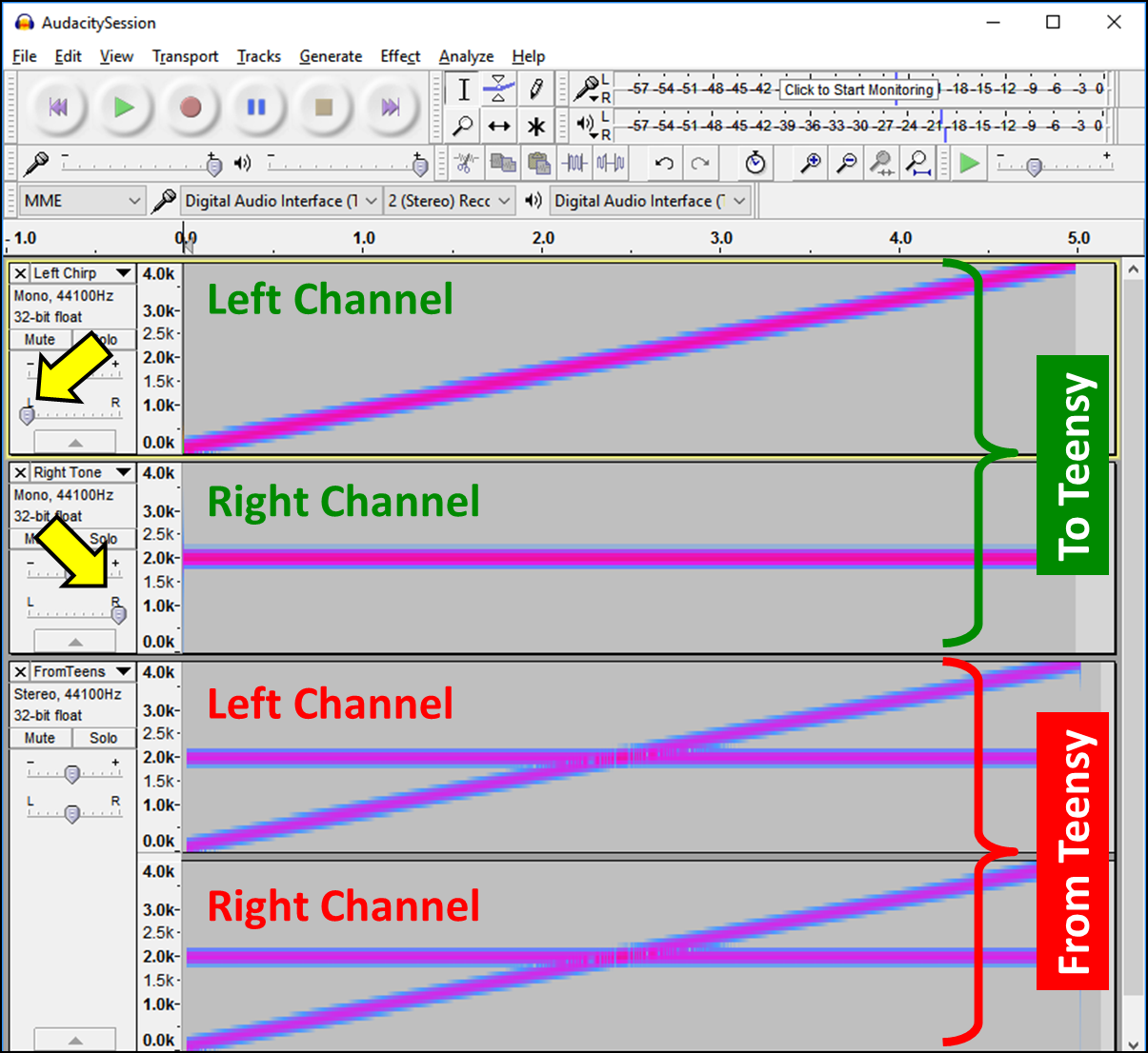
Testing Using Audacity:  To test my example sketch, I used Audacity to generate some test audio and to send the audio to my Teensy 3.6 via the Teeny's USB audio connection.  For my test audio, I created an upward sweeping chirp for the left channel and I created a steady 2 kHz tone for the right channel.  In the screenshot below, the yellow arrows point to the panning controls that I used to force my audio into the left and right channels.


Result:  Hitting the record button, Audacity played the stereo audio out to the Teensy while simultaneously recording the audio being output by the Teensy.  As you can see, the audio produced by the Teensy was the mixture of the left and right inputs.  Success!

Many Thanks:  I'm so appreciative for Patrick's high-quality contributions to this library.  Many, many thanks.  And, from him or from anyone elese, I greatly look forward to additional Pull Requests!

Tuesday, October 25, 2016

Teensy Audio over USB

In my last post, where I sent my first analog audio through a Teensy, I also discovered that it has the ability to exchange digital audio over its USB link.  Whoa.  This means that, if I'm developing some snazzy new audio-processing algorithm, I can test it 100% digitally without adding any complications of converting back and forth through analog signals.  That is a really powerful capability that'll greatly simplify my audio development.  Let's see if it really works!


Discovering USB Audio:  I only discovered that the Teensy might be able to do USB Audio while using their web-based graphical tool.  This is a tool that the Teensy folks ahve created to help people work with their Audio Library.  While using that tool, I noticed that there were input/output blocks named "USB".  Does this mean that Teensy can exchange audio over USB?!?  Really?  That's a pretty advanced feature for an electronics board aimed at hobbyists!  Does it work?

A Simple USB Audio Chain:  To give it a try, I configured an audio chain as shown below: one stereo USB input connected to one stereo USB output.  The left channel is just connected straight across -- no processing.  For the right channel, though, I've inserted a Biquad filter block just so that I can confirm that the Teensy is indeed doing something to the audio.  It's a pretty simple setup.


It Didn't Work:  When I exported the audio chain above, loaded it onto the Teensy, and gave it a try, it didn't work.  I got silence.  I don't know why.  So I started messing around...

Making it Work:  To get the USB Audio to work, I found that I had to engage the audio board's hardware in some way.  One way to make it work is shown below: add a SGTL5000 block for the Audio Board, and add an I2S block to be the output of the Audio Board.  I connected the I2S output to be just like the USB output.  Now, whatever the Teensy is sending out via USB will also be present at the headphone jack.  Sure, it seems like an unnecessary complication if I just want to use USB for my audio, but it's kinda cool that it's so easy to output to multiple targets simultaneously.


Completing the Arduino Code:  The graphical web-based tool shown above doesn't produce a complete program to load onto the Teensy -- it just gets you started.  When I hit the "Export" button, it gave me all of the code to setup the hardware and make the connections, but I still needed to write the last bit of code to make it run.  As usual, I did my coding in the Arduino IDE because it's easiest.

My Code:  The screenshot below shows the Arduino sketch that I used for this demo (it's on my GitHub here).  At the top is the big block of code that was exported from the web-based tool.  Easy.  Then, at the bottom, I added the setup() and loop() functions.  As you can see, the setup() function configures the SGTL5000 audio board and it sets the biquad filter to be a low-pass filter at 500 Hz.  The loop() function does nothing.


Tell the Compiler about USB Audio!  The only trick to using the USB audio is that you need to tell the compiler that you want the Teensy to run in USB Audio mode.  So, prior to compiling and uploading this Arduino sketch, go under the "Tools" menu, click on "USB Type" and select "Audio".  Notice that there are many other choices, including "Serial", "Keyboard, "MIDI", "Audio" and "No USB".   Normally, one uses "Serial" so that Serial.println() is able to print messages to the Serial Monitor.  But, for this demo, I want "Audio".


Loading onto the Teensy:  Once you change the USB setting to Audio, you can compile and upload to the Teensy.  The first time you do it, it'll probably upload to the Teensy without any issue.  Great!  But, once it is in USB Audio mode, future programs won't appear to upload automatically.  Why?  Well, once the USB link set for Audio, the Teensy can't get reprogramming commands over that same USB link.  What's the solution?  After the Arduino IDE has finished compiling, simply press the Teensy's reset button (picture below).  After a reset, the Teensy knows to check in with the PC prior to switching over to Audio mode.  It will automatically get any new program waiting for it.  It's a small extra step, but I didn't find it to be a problem at all.


Testing Using Audacity:  Once the Teensy is in USB Audio mode, the Teensy appears to your PC as if it is a soundcard.  So, you can now send and receive audio data to it using any audio recording program.  For this demo, I used Audacity because it is free.

Configuring Audacity:  With the Teensy attached, my computer now has two soundcards: (1) its built-in soundcard and (2) the Teensy.  Once Audacity launches, I configured Audacity to use the Teensy as the soundcard instead of the built-in one.  The screenshot below shows the five settings that I changed in Audacity.  On my computer (Windows 7), the Teensy cryptically appeared as "Digital Audio Interface (2-Tee" [sic], which wasn't as quite helpful as informative as it could have been, but it was good enough for me to choose the right item.


First USB Audio:  For this test, I'm want to send audio out over USB (to the Teensy) and record audio coming from USB (from the Teensy).  So, I need to start by creating a test signal to send out over USB.  Under the "Generate" menu, I chose "Chirp" and made a linear frequency sweep from 100 Hz to 4000 Hz.  This appeared as a single mono track in Audacity.  That's all the preparation that I needed to do.  Now, I simply hit the red record button.  Audacity started playing out the chirp audio to the Teensy while recording the audio coming back from the Teensy.  The result is shown in the screenshot below.


Success!  The screen shot shows two audio files.  Both files are shown in "spectrogram" view (60 dB dynamic range).  The top file contains the original (mono) frequency sweep generated by Audacity.  This is what was sent to the Teensy over the USB Audio link.  The bottom file shows the stereo audio recorded from the Teensy.  The left channel had no processing being performed by the Teensy and it does indeed appear to be a copy of the original signal.  The right channel, though, was being processed by the Teensy by its 500 Hz low-pass biquad filter.  As can be seen, the high frequencies are attenuated -- the gentle roll-off is as expected from a biquad filter.  This was amazingly easy!

Future Use:  While I'm very impressed that this capability exists at all, it's not perfect.  In additional testing, I occasionally found hiccups or other artifacts in the audio stream coming back from the Teensy.  But, most of the time, this USB Audio link worked really well.  It'll be great for debugging my audio projects.  Anytime I have any question about the negative effects of my analog components, I can simply switch over to USB Audio to avoid the whole problem.  It'll be a great tool to have in my audio hacking toolbox.